


 English
 中文简体

Machinist Symbols Guide: Reading Blueprint Marks for Precision CNC Parts
Content
Machinist symbols can look like a foreign language when you open a production drawing for the first time. After more than three decades of machining precision components, we can tell you that the most expensive mistakes rarely come from complex geometries. They come from small symbols read incorrectly. That is why every machinist at Xierge Precision Machinery Co., Ltd. starts a new job by studying the drawing rather than switching on the machine.
A surface finish mark, a datum callout, or a true position tolerance changes the sequence of operations, the choice of tools, and even the type of CNC lathe or grinding machine we assign. Reading machinist symbols correctly is not a paperwork exercise. It is the difference between a part that serves reliably for years and a part that fails during validation.
The term covers more than roughness and geometry. It includes surface texture, edge conditions, datum reference letters, and even notes about burrs and sharp corners. A drawing that combines all these is complete enough to machine without guesswork, and that is exactly what a precision shop hopes to receive.
Surface Finish Machinist Symbols: The First Clue
Surface finish is usually the first group of machinist symbols that a shop searches for on a drawing. A standard roughness value such as Ra 0.8 µm or Ra 1.6 µm tells the operator how smooth the final surface must be. These symbols also affect cost. Finer surfaces require additional grinding passes, careful wheel selection, and sometimes a separate cylindrical grinding operation.
| Symbol | Meaning | Typical Application |
|---|---|---|
| Ra 1.6 | Average roughness of 1.6 micrometres | General mating surfaces |
| Ra 0.8 | Average roughness of 0.8 micrometres | Sealing faces and shaft journals |
| Lay direction | Orientation of surface marks | Bearing seats and seal rings |
| Waviness | Longer-wavelength surface profile | Ground and lapped parts |
In CNC automotive parts, a shock absorber sleeve needs a controlled finish to slide smoothly and stay reliable. If the drawing says Ra 0.8 and the shop treats it as Ra 1.6, the component may still measure within size but wear out too early. That is why our engineers confirm the surface finish symbol before quoting, especially for products with long service expectations.
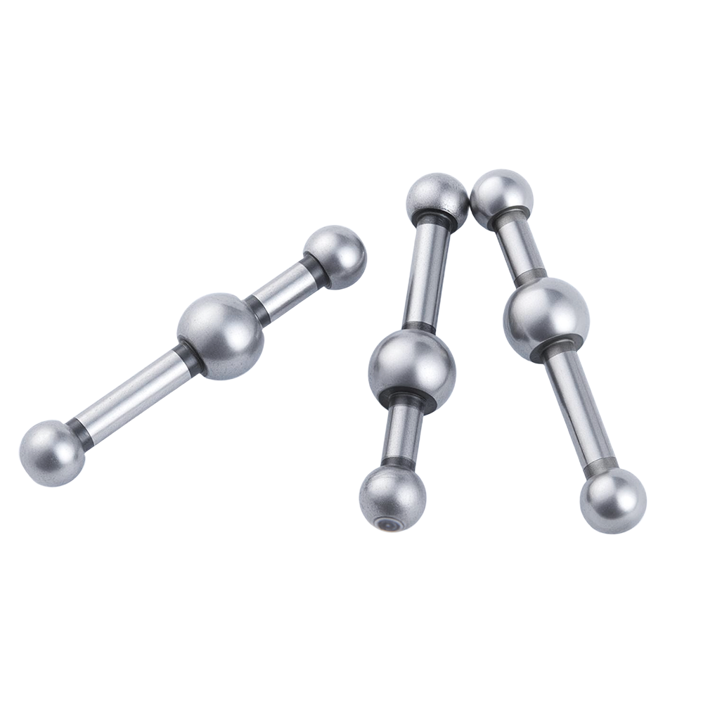 Precision Machined Automotive Parts for Reliable PerformanceExplore shafts, sleeves, and valve components with exact finishes. The category page links surface roughness callouts to long service life and dependable quotes.View Product →
The symbol itself is only half of the message. The lay direction, the measurement unit, and notes such as "no polishing" or "machine marks allowed" all change the production plan. Experienced machinists read the whole tolerance block, not just the apparent symbol.
GD&T Machinist Symbols That Determine Assembly
Geometric dimensioning and tolerancing is where machinist symbols become truly valuable. Size tolerances tell you how big something is. GD&T tells you how one feature sits relative to another, and that is what actually decides whether assembly works.
| Symbol | Name | Controlled Characteristic |
|---|---|---|
| Flatness | Surface evenness | Form of a surface |
| Parallelism | Equal distance to a datum | Orientation |
| Perpendicularity | Squareness to a datum | Orientation |
| True position | Location of a hole or pin | Location |
| Concentricity | Alignment of midpoints | Coaxiality |
A true position callout on a locating pin, for example, allows the centre of the hole to drift inside a defined tolerance zone. A perpendicularity symbol on a valve stem controls whether the stem tilts when it enters a mating bore. Both are classic machinist symbols that a Swiss-type CNC lathe can hold consistently, provided the setup and clamping are correct.
New customers sometimes ask whether these symbols really matter for small production batches. They do. A feature control frame can look almost the same to an untrained eye but lead to completely different machining sequences. Our team treats GD&T as the contract between the designer and the shop.
A common mistake for designers is to over-specify symbols. Too many constraints with unrealistic values force a machinist to fight the drawing instead of following it. The best drawings combine a clear part function with tolerance ranges that can actually be produced in a regular manufacturing process.
Thread, Datum, and Hole Symbols You Will Meet Daily
Beyond surface finish and GD&T, a production drawing contains a collection of everyday machinist symbols that still cause confusion during quoting. Thread classes, datum identifiers, countersinks, counterbores, chamfers, and edge conditions must all be read together.
- Thread callouts such as M6 x 1.0 - 6H define the tolerance class and fit of the thread.
- Datum symbols labelled A, B, or C establish the reference points for every geometric tolerance on the drawing.
- Countersink and counterbore symbols define the exact profile needed for a fastener head to sit flush.
- Chamfer and radius callouts control edges that might contact, seal, or need deburring.
Material callouts often appear alongside the symbol. Brass, aluminum alloy, and stainless steel respond differently to the same surface finish requirement, so the machinist must read the material block and the symbol together.
These are the machinist symbols that produce the most questions during quoting. We often see drawings where the thread class is missing, a datum is placed on the wrong surface, or a chamfer dimension conflicts with a countersink angle. Catching these small issues before production saves days of back-and-forth communication.
What Happens When a Machinist Misreads a Symbol
Misreading a symbol usually costs time before it costs money. The machinist sets up the machine, runs test pieces, and only then discovers that the feature control frame requires a different interpretation. Scrap rates climb, and delivery dates move.
- A missing roughness unit leads to a surface ten times rougher or finer than intended.
- A datum left unmarked shifts every subsequent tolerance to the wrong reference.
- A perpendicularity callout treated as flatness creates angled mating faces.
- An ignored thread tolerance causes the part to seize or wobble during assembly.
In liquid cooling components, sealing faces depend on fine finish, flatness, and concentricity at the same time. One misread symbol can mean a leak under pressure. Because these parts go into pumps, connectors, and cooling plates, our machinists always confirm ambiguous callouts before cutting the first chip.
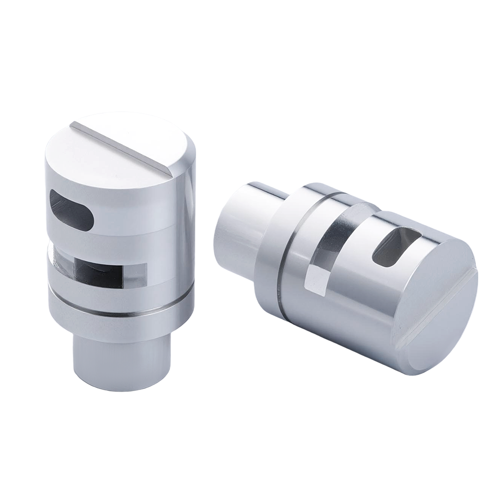 CNC Liquid Cooling Components with Tight Tolerance ControlSealing faces require fine finish and concentricity. These pump, connector, and cooling plate parts demand precise machining to prevent pressure leaks.View Product →
The same logic applies to locating pins, bearing rings, sleeves, and many other precision-turned parts. When a customer sends a drawing with symbols that can be read in two ways, clarifying the intent is part of the job. Guessing is not.
Nobody wants to scrap a batch after running it overnight. That is why shops that invest in measurement equipment and operator training consistently deliver better parts. In our workshop, imported measuring instruments are used alongside the same drawing to verify each critical symbol.
Why We Treat Machinist Symbols as Part of the Contract
Choosing a machining supplier is not only about machine size and price. It is about whether the operators truly understand what the drawing intends. Since 1990, Xierge Precision Machinery Co., Ltd. has produced turned parts, ground components, and complete assemblies for automotive, liquid cooling, power tool, optical, and home appliance industries. Ask a potential partner how they handle the symbols you rarely see.
When a drawing calls for a ground surface, for example, we assign one of our high-precision grinding lines. When a component requires tight rotational symmetry, we evaluate it on the Swiss-type lathe best suited to the material and batch size. This experience matters far more than the symbol vocabulary itself.
For optical instrument parts and other components with micrometre-level requirements, the drawing is nearly sacred. Every symbol carries weight, and skipping one question leads to expensive surprises.
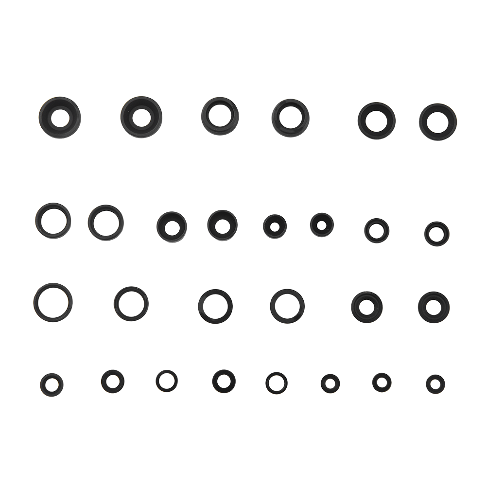 High-Precision Optical Components with Micron-Level AccuracyOptical shims and spacers control lens spacing and imaging stability. Reviewing drawing symbols here prevents costly surprises in micrometre-level production.View Product →
The best time to discuss machinist symbols is before you send the final purchase order. If your drawing contains a callout you are unsure about, ask the supplier how they will hold it and how they will measure it. A reliable CNC machining service will give you a straight answer.
Pricing is easier when the drawing is complete. If you submit a drawing with missing symbols, we will ask questions instead of inventing answers. That protects your schedule and your budget.
At Xierge, we welcome new drawings with unfamiliar symbols. Send us your drawing, and our engineers will work through every mark with you. When machinist symbols are clear, machining becomes predictable, and that is how precision components should be made.
-
Why Does CNC Precision Machining Matter for Automotive Parts?
What CNC Precision Machining Brings to Automotive Parts CNC precision machining matters for automotive parts because it removes material from a solid workpiece according to a programmed digital path,...
-
CNC Turning and Precision Metal Parts Manufacturing
CNC Turning and Precision Metal Parts Manufacturing Precision CNC machining is an essential process for manufacturing metal components used in a wide range of industrial applications. From aluminum pa...
-
CNC Precision Machined Automotive Parts: Materials, Tolerances, and How to Choose the Right Manufacturer
CNC precision machined automotive parts are components produced by computer-controlled subtractive manufacturing processes — turning, milling, drilling, grinding, and multi-axis machining — to dimensi...
-
The Role of CNC Precision Machining in Manufacturing High-Performance Power Tool Parts
What Is CNC Precision Machining CNC precision machining is a computer-controlled manufacturing process that removes material from metal or plastic blanks using cutting tools to produce parts with ext...
-
Design for CNC Machining: Practical DFM Guidelines for Precision Manufacturers
Designing for CNC machining is not simply about creating a 3D model that looks right. It is about making sure that every wall, hole, corner, and tolerance can be produced accurately, repeatedly, and ...
-
CNC Precision Machined Automotive Parts: Materials, Tolerances & Applications
Every confident start on a winter morning, every quiet stretch of highway, every smooth brake application depends on hundreds of small metal parts doing their jobs without complaint. That is the worl...

- Products
- CNC Precision Machined Automotive Parts
- CNC Precision Machined Liquid Cooling Parts
- CNC Precision Machined Power Tool Parts
- CNC Precision Machined Optical Components
- Customize
- Swiss Turning
- Machining Center
- CNC Milling&Turning
- Centerless Grinding Machine
- Cylindrical Grinding Machine
- Contact
-
-
TEL: +86-0574-62480516

-
E-mail: [email protected]

-
Phone: +86-13175199595

-
Address: Address: No. 6 Shiji 1st Road, Mazhu Doumen Development Zone, Yuyao City, Zhejiang Province, China

-

